Potential Transformer Wiring Diagram
Battery charger transformer wiring diagram. The primary current is independent of the conditions of the secondary circuit.
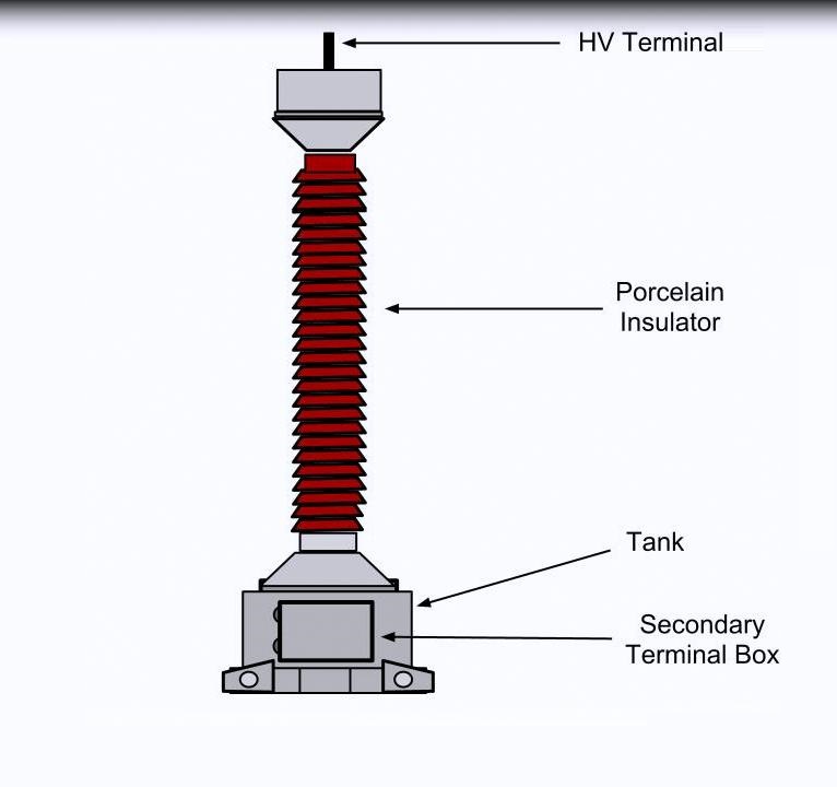
potential transformer Sketch EEE PROJECTS
The voltage applied to the primary of the intermediate transformer is usually of the order 10kv.
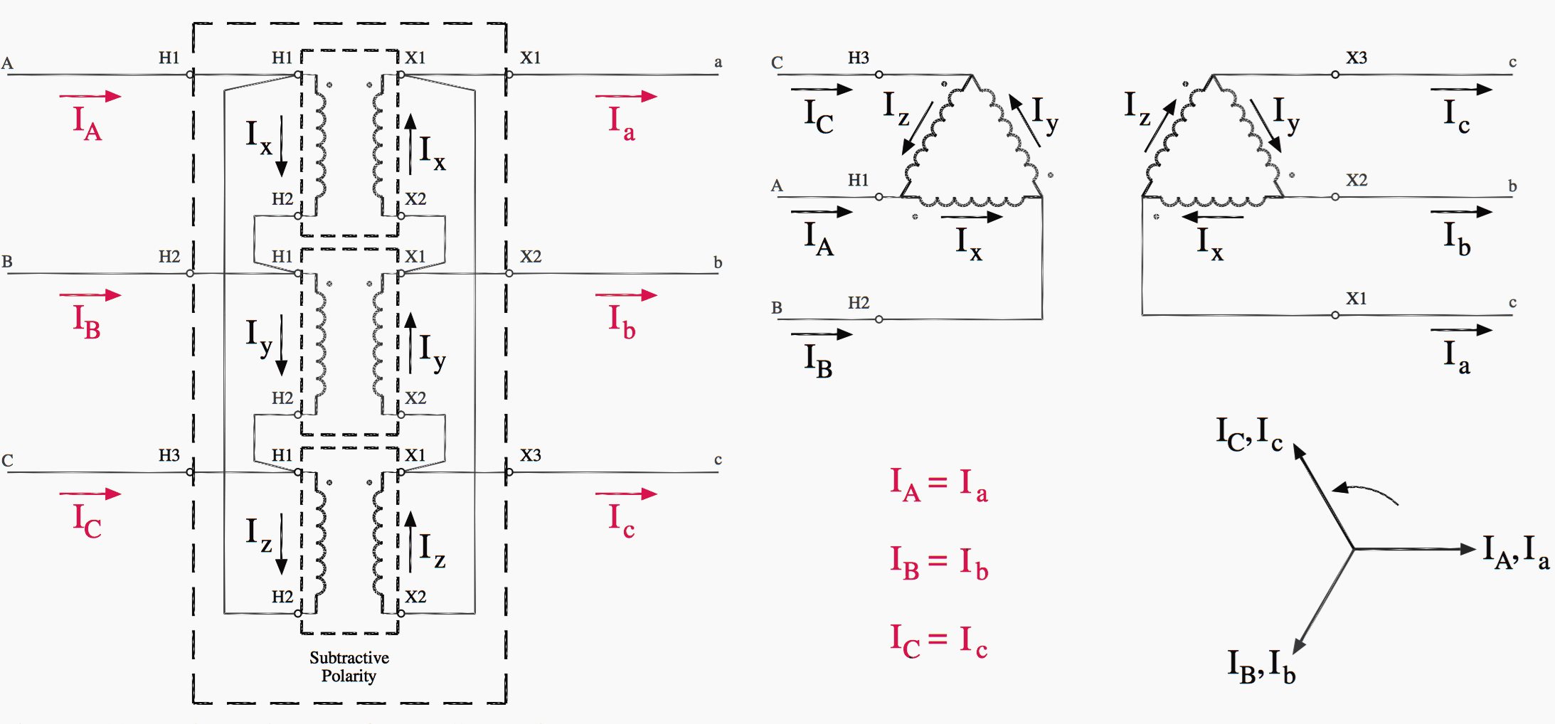
Potential transformer wiring diagram. Injunction of two wires is usually indicated by black dot to the intersection of 2 lines. The phasor diagram at the lower right shows the geometric relationships between the high voltage circuit and low voltage circuit currents, and the equations at the bottom center show those relationships mathematically. The first element is emblem that indicate electrical element in the circuit.
The winding is impressed with full voltage. Basic connection of voltage / potential transformer phase/phase: Α= phase angle between vs and v2 c1 = capacitance of main capacitor (see fig.
Vs and v2 are volts defined as in fig. The circuit diagram of the capacitor potential transformer is shown in the figure below. The stack of high voltage capacitor from the potential divider, the capacitors of two sections become c 1 and c 2, and the z is the burden.
I would like to re wire it and test it. A potential transformer (also known as voltage transformer) is a type of instrument transformer. If the losses in the network are neglected, equation
To control voltage drop in low voltage landscape lighting systems there are two things to consider. According to previous, the lines at a 24 volt transformer wiring diagram signifies wires. It gives 12 volt and 5 amps current for quick charging of the battery.
Another thing you will find a circuit diagram could be traces. Generalgeneral electrical connection diagramsacme® transformer™ wiring diagrams primary: The charger must be grounded to the ac system ground for personnel safety.
The connection diagram of this configuration is shown in the figure below. Primary connected between a phase and the earth. The transformer works on the principle of faradays law of electromagnetic induction and mutual induction.
Occasionally, the cables will cross. However, it doesn't imply connection between the wires. Primary connected between two phases phase/earth:
Figure 2 delta delta transformer connections click to expand diagram. Requires 1 isolated mv terminal for each transformer. With this kind of an illustrative guidebook, you will be capable of troubleshoot, stop, and complete your tasks without difficulty.
There'll be principal lines that are represented by l1, l2, l3, and so on. Low voltage transformer wiring diagram. And primary winding a1a2 corresponds to secondary winding a1a2.
Transformer wiring diagrams are printed on the. On the secondary side low voltage taps of the transformer each circuit has its own magnetic circuit breaker toggle switch that is connected to a common tap marked with a label com. Auto battery charger for 6 or 12 volt sytems.
How to connect pt in in circuit The output voltage of the potential transformer can be measured by connecting an ordinary voltmeter. A circuit is generally composed by several components.
14 schematic diagram of transformer. The secondary winding is noted as a1a2, b1b2, and c1c2. Terminals a1 and a1 have the same polarity.
There are just two things that will be found in almost any low voltage lighting transformer wiring diagram. The primary current is dependent on the conditions of the secondary circuit. The schematic diagram at the upper right is perhaps easier to analyze, as the delta connections can clearly be seen.
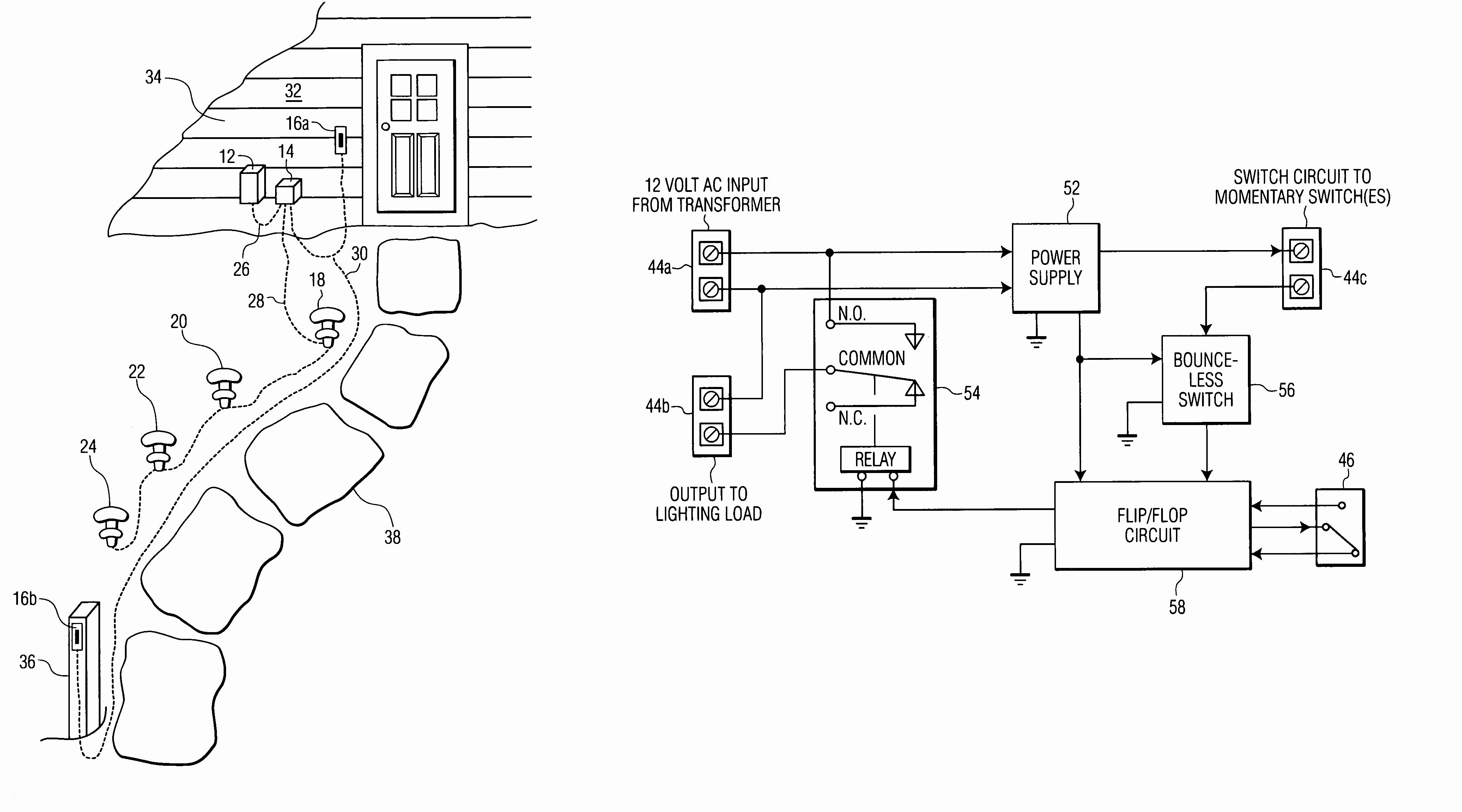
Low Voltage Lighting Transformer Wiring Diagram Cadician's Blog

Instrument Transformers What is it? (and their Advantages) Electrical4U
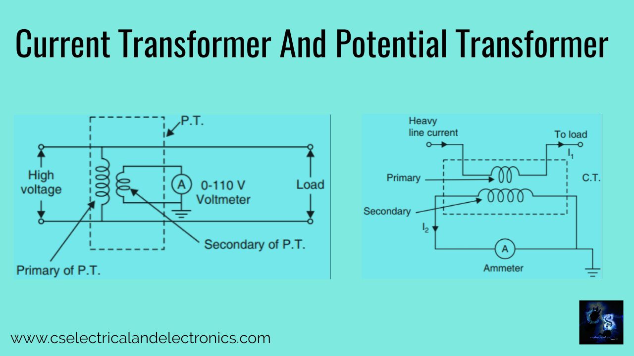
Current Transformer And Potential Transformer, Circuit Diagram, Working
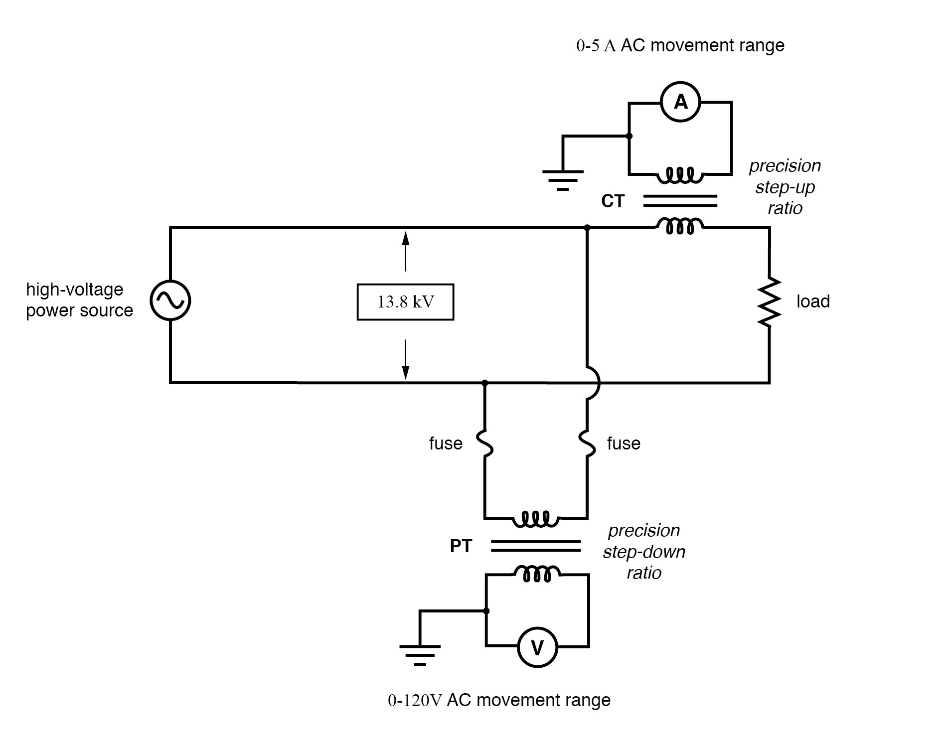
Current Transformer Wiring Diagram My Wiring DIagram

Multi Ratio Current Transformer Wiring Diagram Free Wiring Diagram

Current transformer physical wiring diagram Knowledge Dalian Huayi Electric Power Electric

Low Voltage Transformer Wiring Diagram Download
Three Phase Transformer Connections Phasor Diagrams Electrical Academia

Using Potential Transformers Continental Control Systems, LLC

Difference between Current Transformer & Potential Transformer Electrical Concepts
Phasor Diagram Of Potential Transformer

Capacitive Voltage Transformer Electrical4u
Difference between Current Transformer and Potential Transformer Electrical Academia

Industrial Control Transformer Wiring Diagram Free Wiring Diagram
480V To 120V Transformer Wiring Diagram Collection

Using Potential Transformers Continental Control Systems, LLC

Working of Potential transformer The Electrical Portal

Low Voltage Transformer Wiring Diagram Download
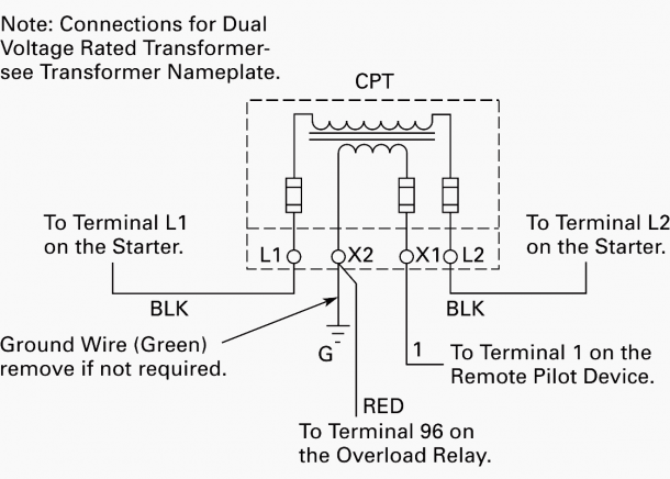
Wiring of control power transformer for motor control circuits EEP

